Supreme Info About How To Double Voltage With Capacitor

Capacitor Voltage Booster Circuit
Boosting Your Voltage
1. Understanding Voltage Multiplication
So, you're curious about how to double voltage with a capacitor? That's a clever question! Let's dive right in. The basic idea revolves around cleverly arranging capacitors and switches (or diodes acting as switches) to charge capacitors in parallel and then discharge them in series. Think of it like this: you're filling up a bunch of small buckets (capacitors) separately and then pouring them all into one big bucket (the output) to get a higher water level (voltage).
It's not quite magic, though. You aren't creating energy from thin air! Instead, you're trading current for voltage. You'll get double the voltage, yes, but at roughly half the current (ideally, anyway; losses always creep in). It's like using a lever: you get more force on one end, but you have to move the other end a greater distance. Energy is conserved; it just gets rearranged.
One common way to achieve this doubling effect is with a charge pump circuit, often called a voltage doubler. This circuit uses diodes and capacitors in a specific arrangement to achieve voltage multiplication. The most well-known topology is the Cockcroft–Walton voltage multiplier (also known as the Greinacher multiplier). It's been around since the early 20th century!
Essentially, during one phase of a switching cycle, the capacitors are charged in parallel, and during the other phase, they're connected in series to deliver the increased voltage to the output. Diodes act as one-way valves, ensuring the charge flows in the right direction. Think of them as tiny traffic cops for electrons!

Capacitors In Parallel
How a Capacitor-Based Voltage Doubler Works
2. Diving into the Circuit
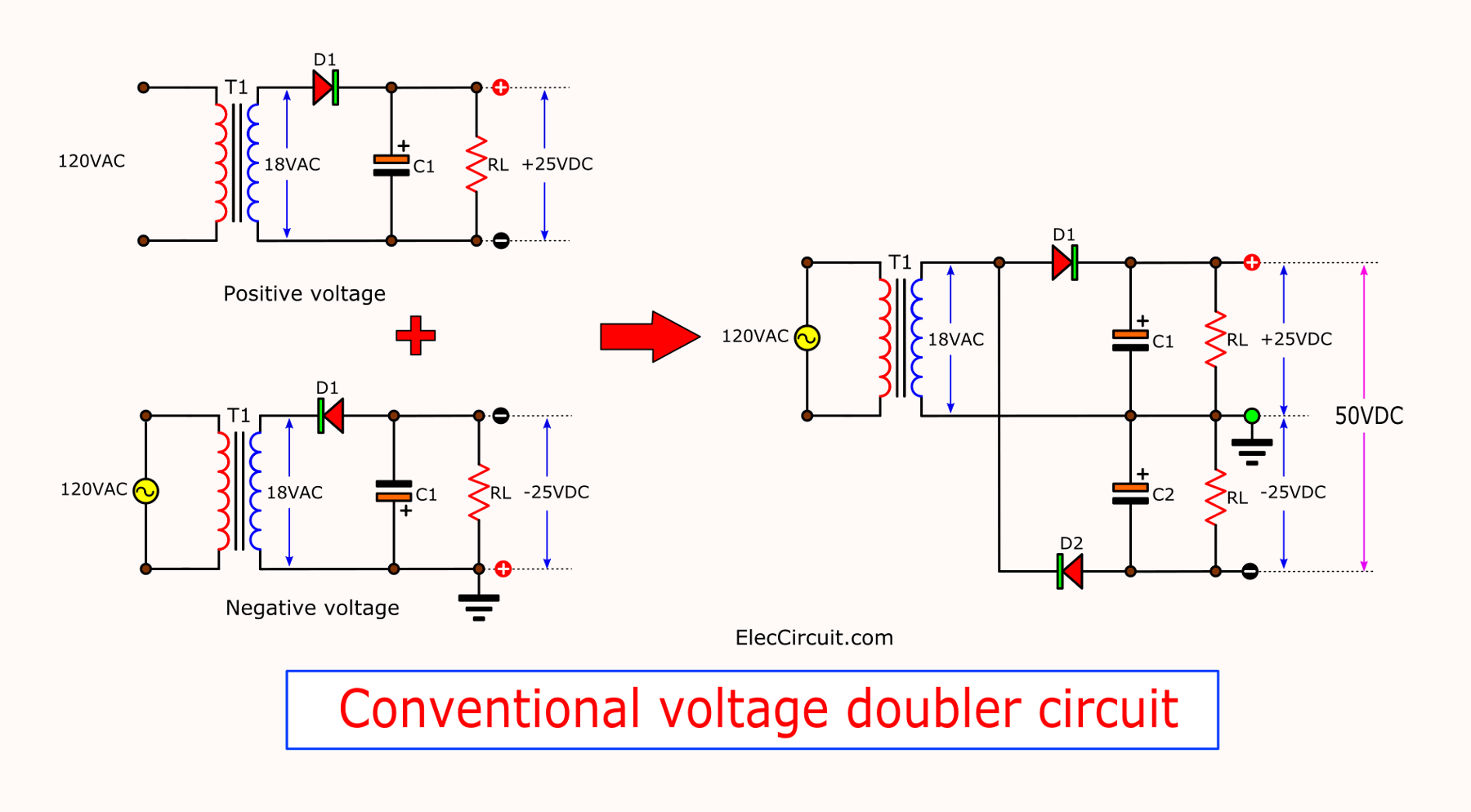
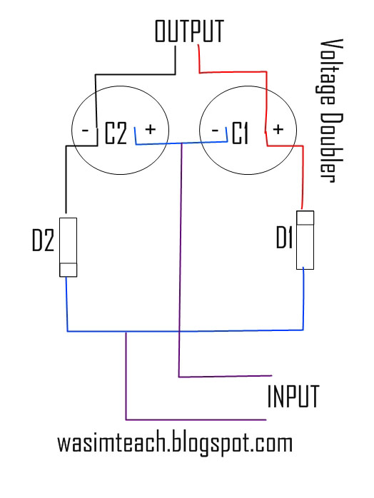
Let's picture a simple voltage doubler circuit. It typically consists of two capacitors and two diodes arranged in a clever configuration. Imagine two parallel paths, each containing a capacitor and a diode. An oscillating input voltage (usually a square wave or similar) is applied to this arrangement. During one half-cycle of the input, one capacitor charges up to the peak input voltage through one diode. During the next half-cycle, the second capacitor charges up, but this time, it's charging in series with the first capacitor. Thus, the voltage across the two capacitors in series effectively doubles the input voltage.
The diodes are crucial because they prevent the charge from flowing backward. They act like one-way streets, ensuring that the capacitors charge in the right direction and that the output voltage doesn't collapse when the input voltage drops. Without the diodes, the capacitors would simply discharge back into the source, and you wouldn't get any voltage multiplication.
The efficiency of a capacitor-based voltage doubler depends on several factors, including the frequency of the input voltage, the values of the capacitors, and the load current. Higher frequencies generally lead to better efficiency, as the capacitors can charge and discharge more quickly. However, extremely high frequencies can also introduce losses due to parasitic effects in the components.
It's not a perfect process, of course. Some energy is lost due to the resistance of the diodes and the equivalent series resistance (ESR) of the capacitors. These losses can reduce the overall efficiency of the circuit. So, while you might aim for a perfect doubling, real-world results will always be a bit less. But it's still a very useful technique for generating higher voltages from lower ones.

Practical Applications of Voltage Doublers
3. Where Do We Use Them?
So where can you actually use these voltage-doubling circuits? They pop up in all sorts of places! One common application is in power supplies. Sometimes, you need a higher voltage than what's readily available from the mains. A voltage doubler can step up the voltage to the required level without needing a bulky transformer.
Another area where voltage doublers are handy is in generating high voltages for specific applications like photomultiplier tubes (PMTs) or certain scientific instruments. These devices often require hundreds or even thousands of volts, and a voltage multiplier can provide that boost efficiently.
Even something as simple as a LED flashlight might use a voltage doubler. If the batteries provide a low voltage, a voltage doubler can step it up to drive the LED at its optimal brightness. It's all about maximizing efficiency and performance!
Microcontroller-based systems sometimes incorporate charge pumps for generating specific bias voltages needed for analog circuits or for programming non-volatile memory. The compact size and ease of integration make them ideal for these applications. Plus, they're often more efficient than other methods for generating these specialized voltages.

Wasim Teach How To Make Voltage Doubler , 2X
Limitations and Considerations
4. The Not-So-Shiny Side
While voltage doublers are cool, they're not a magic bullet. They have limitations. The output voltage isn't perfectly stable. It tends to droop, especially when you draw a lot of current. This "droop" is because the capacitors take time to recharge, and if the load is demanding a lot of current, they discharge faster than they can recharge.
The output impedance (resistance to changes in voltage when current changes) is also relatively high compared to a direct voltage source. This means that the output voltage is more sensitive to changes in load current. If you need a very stable and consistent voltage, a voltage doubler might not be the best choice.
There are also losses to consider. Diodes aren't perfect; they have a forward voltage drop, meaning they consume a little bit of voltage when conducting current. Capacitors also have internal resistance (ESR), which contributes to losses. These losses add up and reduce the overall efficiency of the circuit.
Furthermore, the components used in the voltage doubler need to be chosen carefully. The capacitors must be able to handle the voltages involved, and the diodes must be fast enough to switch at the operating frequency. Using the wrong components can lead to poor performance or even component failure. Selecting the right capacitor and diode is crucial to the lifespan and functionality of the design.

Voltage Doubler Circuit Diagram, HalfWave & FullWave
Voltage Doubling vs. Other Techniques
5. Choosing the Right Tool
How does capacitor-based voltage doubling stack up against other voltage boosting techniques, like transformers? Well, transformers offer galvanic isolation, meaning the input and output are electrically isolated from each other. Voltage doublers don't provide this isolation, which can be a safety concern in some applications. Transformers can also handle much higher power levels and are generally more efficient for high-power applications.
Another alternative is using a boost converter, which is a type of switching regulator. Boost converters offer better regulation and efficiency compared to simple voltage doublers. They use an inductor to store energy and then release it at a higher voltage. However, boost converters are more complex and require more components than voltage doublers.
When choosing between these techniques, it really depends on the specific requirements of the application. If isolation is crucial, a transformer is the way to go. If high efficiency and tight regulation are needed, a boost converter is a better choice. But if simplicity, small size, and low cost are paramount, a voltage doubler might be just the ticket.
Ultimately, knowing how to double voltage with a capacitor is a useful tool in any electronics enthusiast's arsenal. It's a clever trick that can solve a variety of voltage-related problems, but it's important to understand its limitations and when other techniques might be more appropriate. The application determines the selection.

Voltage Doubler Circuit Schematic
FAQ
6. Your Burning Questions Answered
Here are some common questions people have about doubling voltage with capacitors:
Q: Can I double any voltage with this method?A: In theory, yes. However, in practice, there are voltage limits imposed by the components you use (capacitors and diodes). You need to make sure they're rated for the voltages involved. There are also practical limits related to the frequency of the switching signal and the current draw of the load. The design needs to be thoroughly assessed.
Q: Is it possible to triple or quadruple the voltage?A: Absolutely! You can cascade multiple stages of voltage doublers to achieve higher voltage multiplication factors. These circuits are often called Cockcroft-Walton multipliers, which are what's used in older TVs to generate the high voltages to power the display. Each stage adds another voltage doubling step, effectively multiplying the input voltage by a higher factor.
Q: Can I use this to power my house?A: Probably not the best idea. While the concept is valid, scaling this up to household power levels would be impractical and inefficient. Transformers are far more suitable for high-power applications like that. Also, the lack of isolation poses a safety risk. For safety and performance reasons, stick to the standard AC power distribution system for your home!